Part4: Arm SME2 Introduction
Part 4 of the series describes the new SME2 multi-vector and Lookup table features and instructions

This blog post is the fourth part of a four-part series. Please see Part 1: Arm Scalable Matrix Extension (SME) Introduction, Part 2: Arm Scalable Matrix Extension (SME) Instructions and Part 3: Matrix-matrix multiplication. Neon, SVE, and SME compared for the earlier parts of the series.
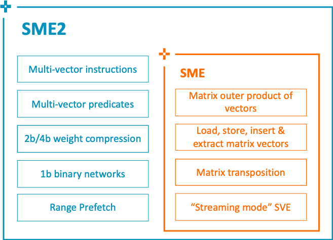
Arm SME2 extends the SME architecture by accelerating vector operations to increase the number of applications that can benefit from the computational efficiency of SME. This is beyond its initial focus on outer products and matrix-matrix multiplication.
SME2 mainly introduces,
- New Multi-vector instructions with Multi-vector predication enable increased vector processing throughput. Furthermore, multi-vector instructions producing results in the ZA array take advantage of Matrix Multiply hardware
- New Lookup Table instructions to decompress 2b or 4b data to 8, 16, or 32-bit containers representing INT8/FP8 from Arm9.5-A, INT16/BF16/FP16, INT32/FP32 by indexing to an architected lookup table
- New Bitwise exclusive NOR population count outer product instructions to support 1-bit Binary Neural Network
SME2 Multi-vector
SME2 Multi-vector instructions support SME2 Multi-vector operands. They are in several categories:
Z multi-vector
The Z multi-vector is a group of two or four SVE Z vector registers with consecutive or strided numbered registers (the stride is +8 with two registers, or +4 with four registers). For example,
- {Z0.S-Z1.S} //a Z multi-vector with consecutive registers
- {Z0.H, Z4.H, Z8.H, Z12.H} //a Z multi-vector with strided numbered registers
ZA multi-slice
The ZA multi-slice is a group of two or four consecutive horizontal or vertical ZA tile slices. For example,
- ZA0H.B[w12, 0:1] // a ZA multi-slice with two horizontal ZA tile slices
- ZA0V.B[w12, 0:3] // a ZA multi-slice with four vertical ZA tile slices
ZA multi-vector
The ZA multi-vector operand consists of one, two, or four vector groups, where a vector group is one of the following:
- a ZA single-vector group: any one ZA array vector
- a ZA double-vector group: two consecutively numbered vectors in the ZA array
- a ZA quad-vector group: four consecutively numbered vectors in the ZA array
The figure below illustrates vector groups in the ZA Array:
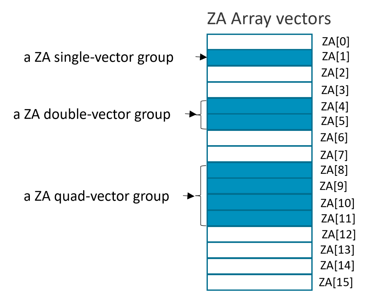
The vector group symbols, VGx2 and VGx4, indicate two or four vector groups respectively.
For instructions that access a ZA multi-vector operand, the lowest-numbered vector is selected by the sum of a 32-bit general-purpose register (vector select register Wv) and an offset (vector select offset offs), modulo one of the following values:
- SVL_B when the operand consists of one ZA vector group.
- SVL_B /2 when the operand consists of two ZA vector groups.
- SVL_B /4 when the operand consists of four ZA vector groups.
Where SVL_B is the number of 8-bit elements in the Streaming vector length.
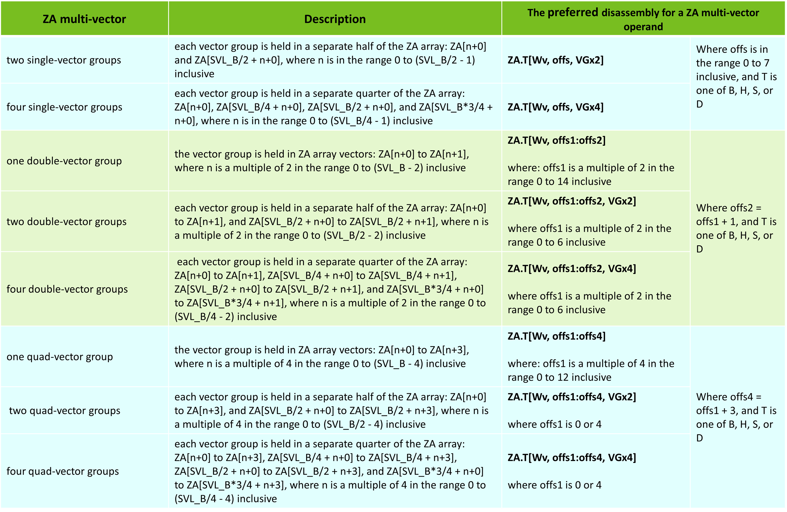
The ZA multi-vector operands are shown in the table below:
To help you understand the ZA multi-vector operand, let us give you some examples.
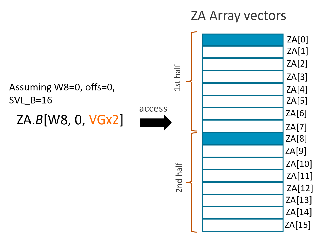
An example of two single-vector groups
A 'two single-vector groups' can be presented as
ZA.T[Wv, offs, VGx2]
Assuming W8=0, offs=0 and SVL_B=16, then ZA.B[W8, 0, VGx2] accesses the ZA array vectors as shown in the figure below:
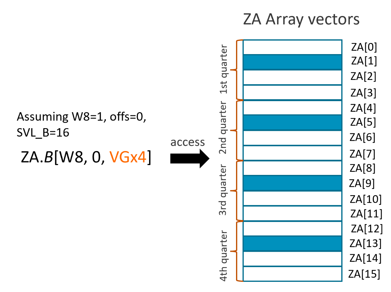
An example of four single-vector groups
A 'four single-vector groups' can be presented as
ZA.T[Wv, offs, VGx4]
Assuming W8=1, offs=0 and SVL_B=16, then ZA.B[W8, 0, VGx4] accesses the ZA array vectors as shown in the figure below:
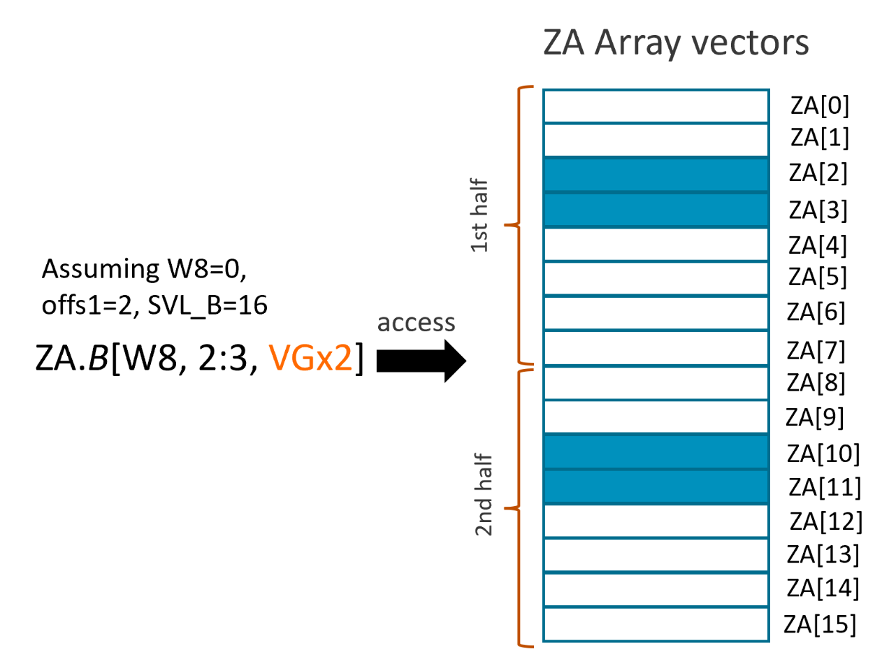
An example of two double-vector groups
A 'two double-vector groups' can be presented as
ZA.T[Wv, offs1:offs2, VGx2]
Assuming W8=0, offs1=2 and SVL_B=16, then ZA.B[W8, 2:3, VGx2] accesses the ZA array vectors as shown in the figure below:
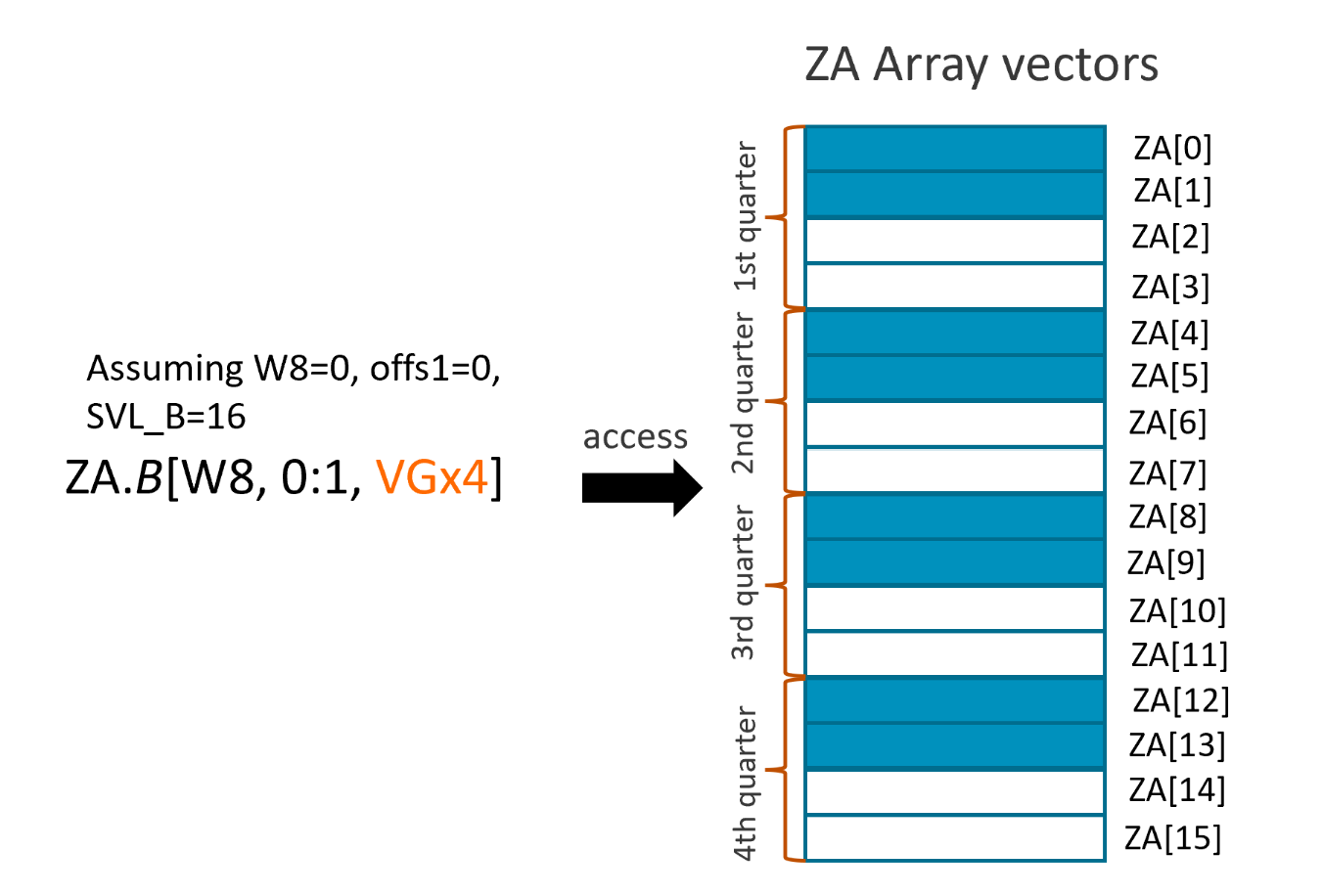
An example of four double-vector groups
A 'four double-vector groups' can be presented as
ZA.T[Wv, offs1:offs2, VGx4]
Assuming W8=0, offs1=0 and SVL_B=16, then ZA.B[W8, 0:1, VGx4] accesses the ZA array vectors as shown in the figure below:
SME2 Multi-vector instructions
The new Multi-vector instructions mainly include:
- Multi-vector load, store, move, permute and convert instructions
- Multi-vector multiply, multiply-accumulate or widening multiply-accumulate, addition, subtract and dot-product instructions
Here are some examples of Multi-vector instructions:
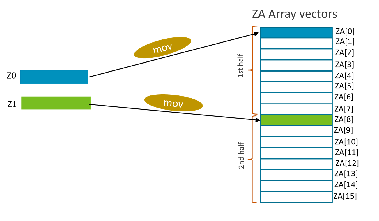
Multi-vector MOVA instructions
Those instructions move 2 or 4 Z register to ZA multi-vector groups, or move ZA multi-vector groups to Z registers. For example:
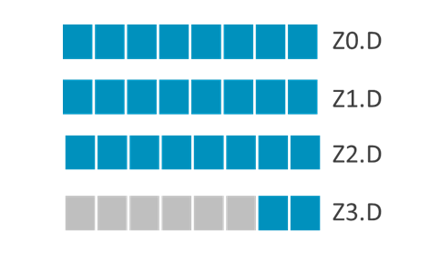
MOVA ZA.D[w8, #0, VGx2], { Z0.D-Z1.D }
This instruction moves two Z registers to a 'Two single-vector groups' as shown in the figure below.
Multi-vector multiply-accumulate and widening multiply-accumulate instructions
Those instructions perform multiply-accumulate or widening multiply-accumulate operations on 2 or 4 Z registers, save result to a ZA multi-vector. For example:
FMLAL ZA.S[W8, 0:1, VGx2], { Z0.H-Z1.H }, Z2.H
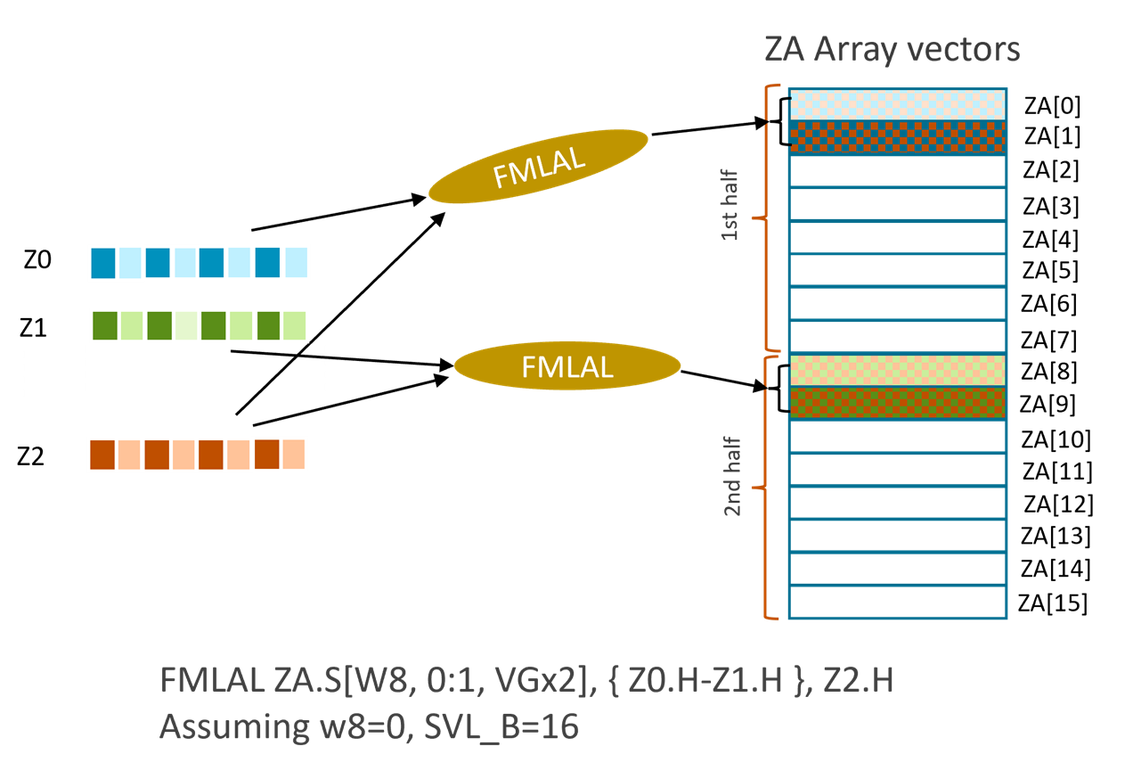
This half-precision floating-point multiply-add long (FMLAL) instruction performs:
- widening multiplication of the even-indexed elements of Z0 and Z2, accumulation of the result of the multiplication with ZA[0], and then store of the final result to ZA[0]
- widening multiplication of the odd-indexed elements of Z0 and Z2, accumulation of the result of the multiplication with ZA[1], and then store of the final result to ZA[1]
- widening multiplication of the even-indexed elements of Z1 and Z2, accumulation of the result of the multiplication with ZA[8], and then store of the final result to ZA[8]
- widening multiplication of the odd-indexed elements of Z1 and Z2, accumulation of the result of the multiplication with ZA[9], and then store of the final result to ZA[9]
Comparing with non Multi-vector FMLAL instructions below,
FMLALB <Zda>.S, <Zn>.H, <Zm>.H
FMLALT <Zda>.S, <Zn>.H, <Zm>.H
The Two ZA double-vectors FMLAL instruction performs twice as many widening multiply-accumulate operations as the combined FMLALB and FMLALT instructions.
With the Four ZA double-vector FMLAL instruction below:
FMLAL ZA.S[<Wv>, <offs1>:<offs2>{, VGx4}], { <Zn1>.H-<Zn4>.H }, <Zm>.H
It provides 4 times the number of widening multiply-accumulate operations than the pair of FMLALB+FMLALT combined.
SME2 Multi-vector predication
To support predication for Multi-vector instructions, SME2 introduced a new method of using existing predicate registers for Multi-vector predication, named 'predicate-as-counter'. The existing SVE predication concept is referred to as 'predicate-as-mask'.
Predicate-as-counter
Predicate-as-counter encodes a consecutive element count in the predicate registers. When a predicate register is used as 'predicate-as-counter', it is named as ‘PNg’, such as PN0.
A PN (predicate-as-counter) and P (predicate-as-mask) register with the same register number, for example PN0 and P0, refer to the same predicate register.
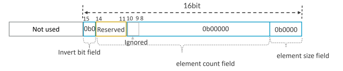
SME2 Multi-vector instructions interpret bits[15:0] of SVE predicate registers as a predicate-as-counter encoding:
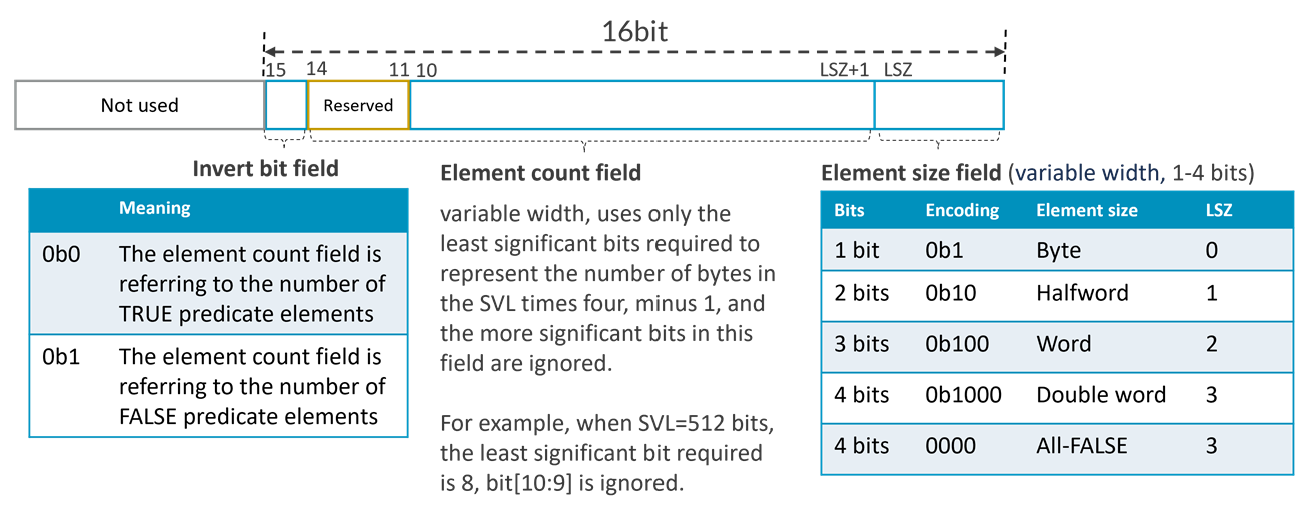
- An invert bit, which encodes whether the element count field refers to the number of TRUE or FALSE predicate elements.
- A variable-width element count field, an unsigned integer value of up to 14 bits, which encodes:
- When the invert bit is 0, the number of consecutive elements starting from element 0 that are TRUE, with the remaining elements being FALSE.
- When the invert bit is 1, the number of consecutive elements starting from element 0 that are FALSE, with the remaining elements being TRUE.
The predicate-as-counter encoding can count up to four vectors of byte elements. Each vector is the largest architecturally defined length, 2048 bits. Ten count bits can count 1024 elements, which is the number of byte elements in four 2048-bit long vectors. So, bit[14:11] is reserved.
- A variable-width element size field of up to four bits, where the number of trailing zeroes (LSZ) encodes log2 of the element size in bytes, or an All-FALSE predicate if all four bits are zero.
Here are some examples,
- Assuming SVL=512b, PNg=0x8001, the predicate register can be decoded with the predicate-as-counter manner as:
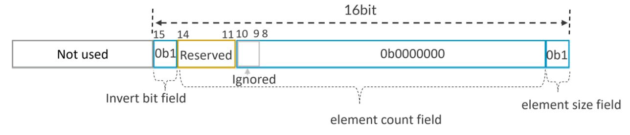 Since the invert bit is 1, the number of consecutive byte-sized elements starting from element 0 that are FALSE is 0, so this is All-TRUE encoding for PNg.B.
 - Assuming SVL=512b, PNg=0x0104, the predicate register can be decoded with the predicate-as-counter manner as:
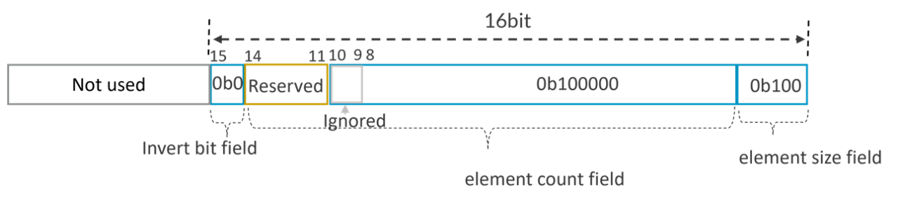
Since the invert bit is 0, the number of consecutive word-sized elements starting from element 0 that are TRUE is 32 (with the remaining elements being FALSE), it is encoding for PNg.S.
- Assuming PNg=0x0, the predicate register can be decoded with the predicate-as-counter manner as:
 This is All-FALSE encoding for PNg (indicated by element size 0b0000), the element size does not matter.
Predicate-as-counter predicate generation
Some instructions such as WHILE, PTRUE, PFALSE are extended to set PN registers. For example:
WHILELT PN0.B, X0, X1, VLx2 // set PN0.B with predicate-as-count encoding according to the while condition
PTRUE PN0.S //set All-TRUE predicate-as-counter encoding for PN0.S
PFALSE PN0.B //set All-FALSE predicate-as-counterencoding for PN0.B
Let me explain the new set of WHILE instructions more.
The new WHILE instructions generate a ‘predicate-as-counter’ predicate. These instructions have an operand (VLx2 or VLx4) that shows the number of vectors (2 or 4) to be controlled by this predicate. This determines:
- The maximum value that can be stored in the count.
- The number of elements that should be considered Active when computing the Any Active element and Last Active element SVE condition flags.
For example:
WHILELT PN0.S, X0, X1, VLx2
The ‘VLx2’ indicates 2 vectors to be controlled by the predicate PN0.S, the ‘LT’ in WHILELT instruction means the condition to test is Less-Than.
This instruction sets PN0 as:
- If X0>=X1, this means that the WHILELT condition is never true
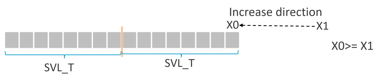 then PN0.S is set to All-FALSE. In the diagram, SVL_T means the number of elements in one vector, where T is the element size specifier such as B,H,S,D.
-
If (X0+2xSVL_T) <= X1, this means that the WHILELT condition will be true for every element of the two (VLx2) vectors.
then PN0.S is set to All-TRUE with element size is set to ‘Word’.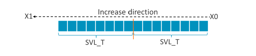
- If X0 < X1 < (X0+2xSVL_T), this means that the WHILELT condition will be true for at least one, but not all of the elements of the two (VLx2) vectors.
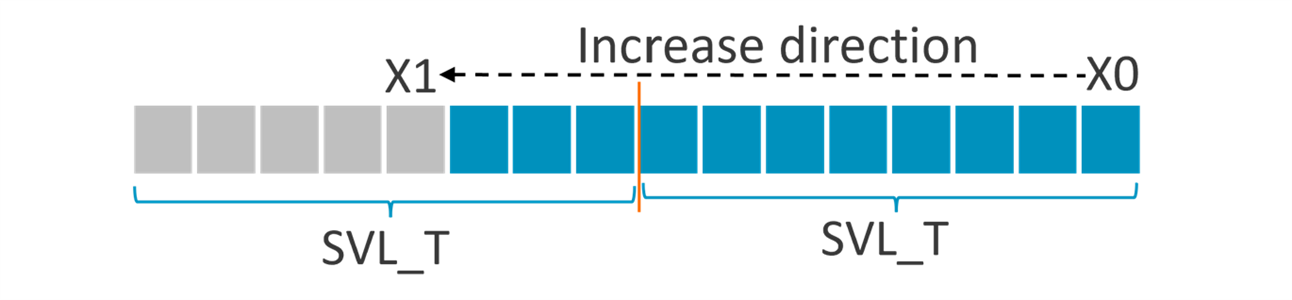
- then PN0.element_count is set to (X1-X0) and PN0.element_size is set to ‘Word’
The generated ‘predicate-as-counter’ predicate can be used by Multi-vector load/store instructions and the Multi-vector select instruction.
For example:
Assuming SVL=512b, PN8.Invert=0, PN8.Element_Count=26 and PN8.Element_Size=Double, then the instruction
LD1D { Z0.D - Z3.D }, PN8/Z, [X0]
reads 26 double words from memory to registers Z0.D-Z3.D with top 6 double words of Z3.D being zeroed.
Here is some example code. To implement C function below:
We can use Multi-vector and ‘predicate-as-counter’ predicate instructions as the code below,
void simple_add_multi_vec(long long *x, unsigned long n)
{
 unsigned long i;
 __asm__ ("smstart \n");
 asm (" mov z1.d, #1 \n"
      "whilelo pn8.d, %[i], %[n], vlx4  \n"
      "1:      \n"
      "ld1d {z4.d-z7.d}, pn8/z, [%[x], %[i], lsl #3] \n"
      "add {z4.d-z7.d}, {z4.d-z7.d}, z1.d \n"
      "st1d {z4.d-z7.d}, pn8, [%[x], %[i], lsl #3] \n"
      "inch %[i]  \n"
      "whilelo pn8.d, %[i], %[n], vlx4  \n"
      "b.any 1b  "
      : [i] "=&r" (i)
      : "[i]" (0), [x] "r" (x), [n] "r" (n)
      : "memory", "cc", "p0", "z1", "z4", "z5", "z6", "z7", "pn8");
  __asm__ ("smstop \n");
}
Besides those new instructions, SME2 adds,
- A new PEXT instruction that converts ‘predicate-as-counter’ predicate to ‘predicate-as-mask’ predicate
- A new CNTP instruction that converts ‘predicate-as-counter’ to a total active element count value
- A new SEL instruction that conditionally selects elements from multiple vectors
SME2 LUTI lookup table
SME2 adds a new register ZT0 and LUTIx instructions.
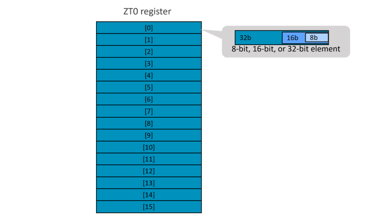
ZT0 register
The ZT0 register has a fixed size of 64 bytes, regardless of the vector length. The register acts as a lookup table that uses 2 or 4 bit indices (compressed weights) to retrieve 8, 16 or 32-bit values from these indices.
The ZT0 register can also be viewed as a lookup table with 16 entries. Each 32-bit entry stores unpacked values that are referenced by the indices. If the unpacked value is 8-bit or 16-bit, it occupies the lower bits of the 32-bit entry.
The ZT0 register can be accessed when ZA array storage is enabled (PSTATE.ZA=1).
SME2 LUTIx instructions
There are two types of lookup table operations:
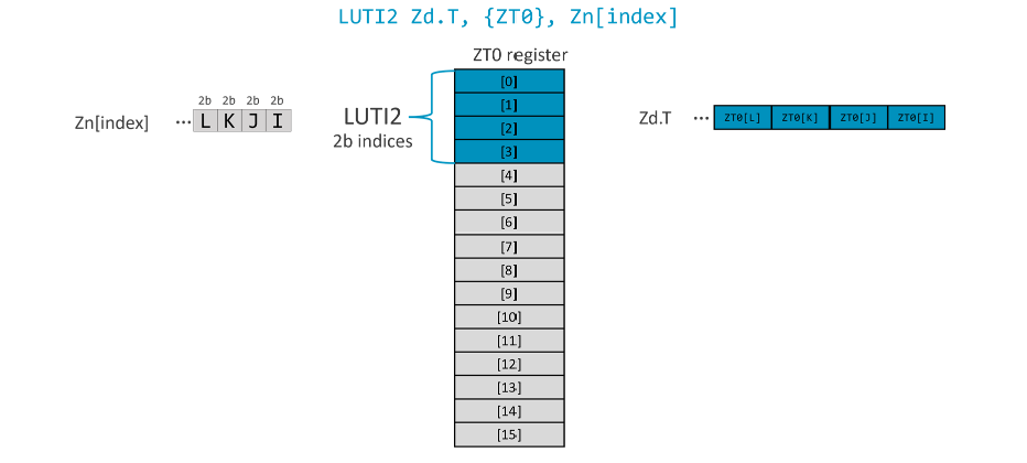
- LUTI2: Indices in the source registers are 2 bits wide, selecting from 4 elements in the ZT0 register. For example:
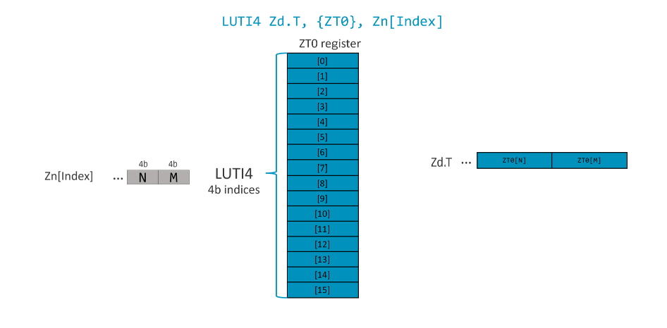
- LUTI4: Indices in the source registers are 4 bits wide, selecting from 16 elements in the ZT0 register. For example:
LUTI2 and LUTI4 instructions can populate 1, 2 or 4 destination registers.
Not all the indices in the source register can be accessed. For example, when SVL=512b, a LUTI2 instruction with 4 destination registers with 32-bit element can produce 64 elements (16 per register). As the indices are 2 bits, 128 bits of the input register are used. The bits needed to store the index values for all of the output elements across each of the destination registers, are called a segment. The instructions have an additional index to select the segment in the input vector (Bit[127:0], [255:128], etc).
Here are some examples of LUTIx instructions. For simplicity of illustration, let us assume SVL=128b.
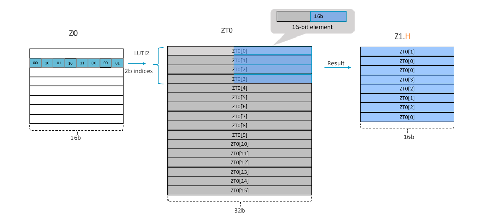
Example 1: LUTI2 Zd.T, {ZT0}, Zn[index]
Take LUTI2 Z1.H, ZT0, Z0[1] for example, as SVL=128-bit and data type is ‘H’, it needs 128/16=8 indexes (each index is 2b) to fill up the destination register. This makes each segment 8x2=16b.
In this example, the ‘index’ is the segment 1. The operation that the instruction performs is illustrated in the figure below:
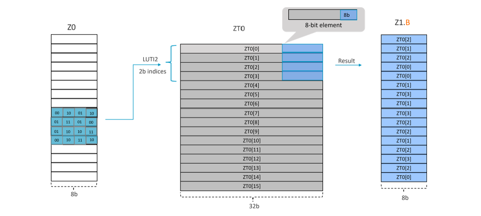
Example 2: LUTI2 Zd.T, {ZT0}, Zn[index]
Take LUTI2 Z1.B, ZT0, Z0[2] for example, as SVL=128-bit and data type is ‘B’, it needs 128/8=16 indexes (each index is 2b) to fill up the destination register. This makes each segment 16x2=32b.
In this example, the ‘index is the segment 2. The operation that the instruction performs is illustrated in the figure below:
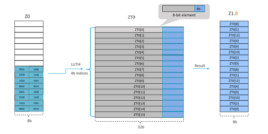
Example 3: LUTI4 Zd.T, {ZT0}, Zn[index]
Take LUTI4 Z1.B, ZT0, Z0[1] for example, as SVL=128-bit and data type is ‘B’, it needs 128/8=16 indexes (each index is 4b) to fill up the destination register. This makes each segment 16x4=64b.
In this example, the ‘index’ is the segment 1. The operation that the instruction performs is illustrated in the figure below:
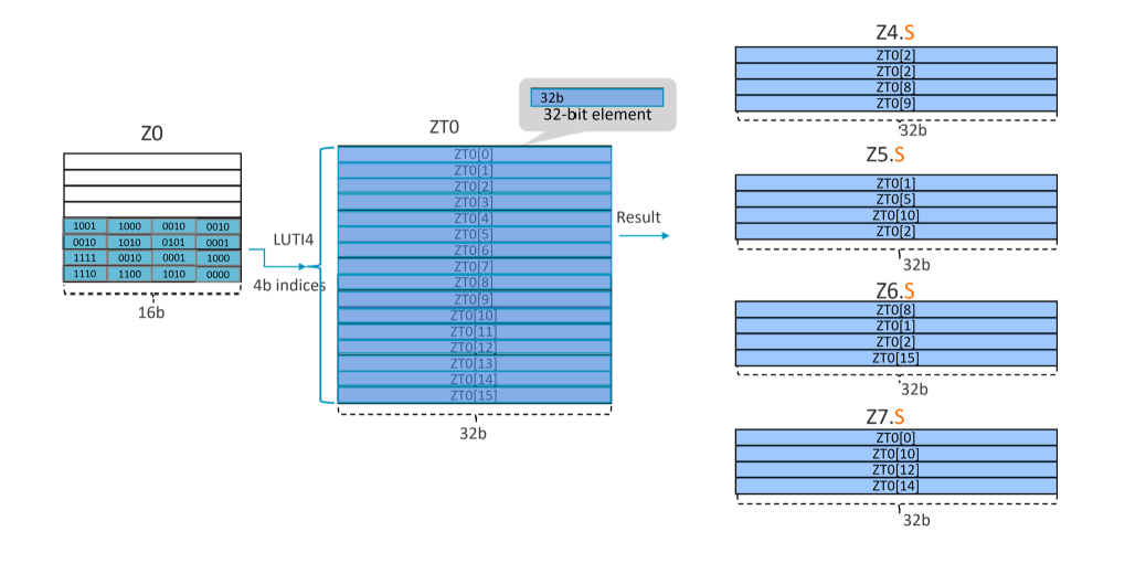
Example 4: LUTI4 { <Zd1>.<T>-<Zd4>.<T> }, ZT0, <Zn>[<index>]
This instruction produces result for 4 destination registers.
Take LUTI4 {Z4.S-Z7.S}, ZT0, Z0[1] for example, as SVL=128-bit and data type is ‘S’, it needs 128*4/32=16 indexes (each index is 4b) to fill up the 4 destination registers. This makes each segment 16x4=64b.
In this example, the ‘index is the segment 1. The operation that the instruction performs is illustrated in the figure below:

Re-use is only permitted for informational and non-commercial or personal use only.
