Test drive the Arm®︎ Cortex®︎-M55 processor using the MPS3 FPGA platform
Using Arm MPS3 FPGA board to test drive Arm Cortex-M55 processor and Corstone-300 system.
By Joseph Yiu
Revision information
| Revision | Update |
| 1 |
Nov 2021 Based on FPGA image AN547 and SSE-300 CMSIS-PACK version 1.2 |
| 2 |
April 2022 Based on FPGA image AN552 and SSE-300 CMSIS-PACK version 1.3 |
Introduction
Since the launch of the Arm Cortex-M55 processor, Ethos-U55 and Corstone-300 in 2020, there has been a strong interest from various parties including Arm partners and the software ecosystem. Recently, Arm has released an FPGA image for the Arm MPS3 FPGA board, called AN552. Details of
- Arm MPS3 FPGA board can be found in Arm MPS3 FPGA prototyping board – Arm Developer, and
- the AN552 FPGA image can be downloaded from FPGA prototyping boards | Download FPGA images – Arm Developer
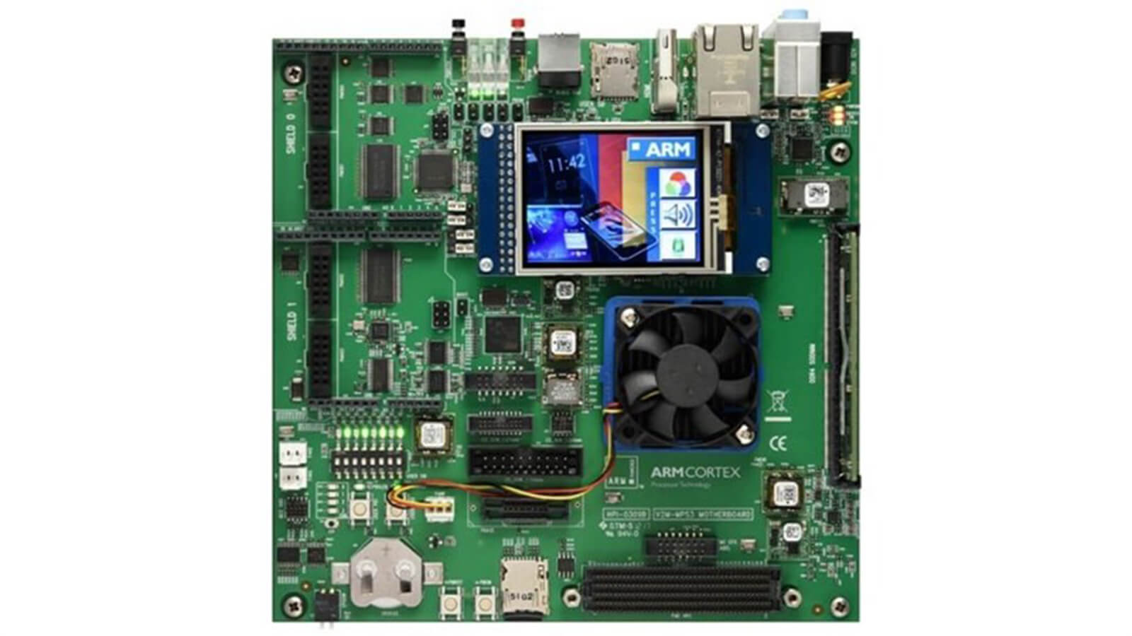
This blog shows you how to test drive the Cortex-M55 processor using the following:
- Arm MPS3 FPGA board
- AN552 FPGA image
- Keil® Microcontroller Development Kit (MDK) version 5.34 or later. Evaluation version of this tool can be download from MDK-ARM Version 5.36 Evaluation Software Request (keil.com)
- Version 1.3 (or later) of the CMSIS-PACK for “Arm SSE-300-MPS3”
The AN552 FPGA image is an update of the previous AN547 FPGA with the following changes:
| AN547 | AN552 | |
| Cortex-M55 Processor | r0 | r1p0 |
| Partial reconfiguration support | no | yes |
| SSE-300 CMSIS-Pack | v1.2 | v1.3 |
With the Partial Reconfiguration feature, the whole FPGA design is composed of an image for a fixed processor FPGA system and an image for user modifiable partition. This arrange allows system designers to redesign the user partition, for example:
- swap/add/remove peripherals
- adding hardware accelerators based on Arm Custom Instructions or Coprocessor interface
As a result of introducing partial reconfiguration, the SRAM's size included in the FPGA need to be reduced. As a result, there are changes to the memory map. Version 1.3 of the SSE-300 CMSIS-PACK support the new memory size settings out of the box. If you are using AN547 FPGA image and have updated the CMSIS-Pack to version 1.3, you might need to manual adjust the memory map settings in your software project.
To download the CMSIS-PACK, you can open the Pack Manager in Keil MDK, locate the SSE-300-MPS3 (SSE-300 is the name of the Cortex-M55 subsystem) and download the pack:
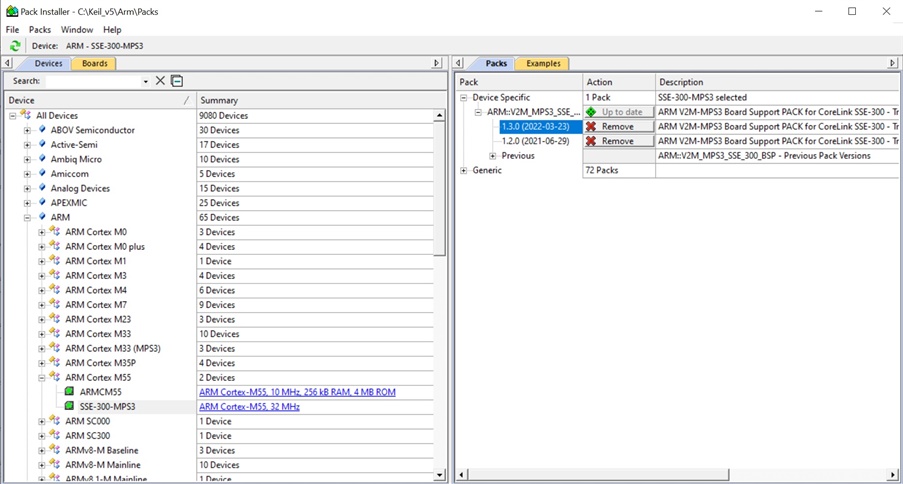
Figure 1: Select and install CMSIS-PACK for AN552 FPGA image.
After you have downloaded the FPGA image (AN552), you need to load the contents of “Board files” directory to the microSD card on the MPS3. This can be done easily by connecting the MPS3 FPGA board to the USB port of your computer, which appears as a USB mass storage.
The application note (a pdf file in “Docs” directory of the AN552) contains the memory map, interrupt assignment and expansion connection details. By default, the processor runs at 32MHz. This can be changed by editing the OSC1 parameter in the configuration file “an552_v3.txt”, which can be found in “Boardfiles\MB\HBI0309C\AN552” directory.
More information about how to use the MPS3 FPGA board is available in the Arm MPS3 FPGA prototyping board Technical Reference Manual (https://developer.arm.com/documentation/100765/0000). You can also find additional information about the MPS3 FPGA board on the MPS3 product page (MPS3 FPGA Prototyping Board – Arm®).
Audio interface
At the back of the MPS3 FPGA, there is a stacked audio connector, providing line-in, line-out and mic-in.
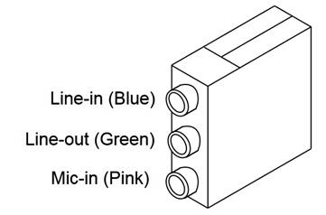
Figure 2: Audio connector on the MPS3 FPGA board
Together with the CS42L52 audio codec chip on board, we can develop audio processing algorithms running on the Cortex-M55 processor, utilizing Helium technology. The audio codec supports 16-bit stereo audio. To support such operations, the AN552 FPGA image contains:
- An I2S interface peripheral that is connected to the CS42L52, located in address 0x59301000 (Secure alias) or 0x49301000 (Non-secure alias). The interrupt number of the I2S is 50 (decimal), and in the vector table the handler’s name is defined as “I2S_Handler”.
- A minimal I2C interface for configuring CS42L52 (operates by bit bang method) which is used only during the audio codec configuration stage. This is located in address 0x59201000 (Secure alias) or 0x49201000 (Non-secure alias). This I2C interface is based on bit bang operations within software, and the device driver utilizes SysTick timer for bit bang timing.
The base addresses of peripherals are defined in the “platform_base_address.h” in the CMSIS-PACK. The vector table (which defines the I2S_Handler) is in the startup code “startup_fvp_sse300_mps3.c”.
To utilize the audio interface, the hardware initialization code needs to:
- Reset the I2S interface.
- Configure the I2S interface.
- Configure the C42L52 audio codec in the I2C interface.
- Enable the I2S interrupt at the NVIC.
After that, the I2S peripheral will interrupt the Cortex-M55 processor periodically. To help with the configuration:
- The CMSIS-PACK for SSE-300-MPS3 version 1.2 included driver codes for I2C and I2S interface.
- The following files “audio_codec_mps3_an552.c” and “audio_codec_mps3_an552.h” are prepared as a part of this application note.
audio_codec_mps3_an552.c:
/*
 * Copyright (c) 2021, Arm Limited. All rights reserved.
 *
 * SPDX-License-Identifier: BSD-3-Clause
 *
 */
#include "SSE300MPS3.h"
#include "cmsis_driver_config.h"
#include "audio_codec_mps3_an552.h"
#include "timeout.h"
#include "device_definition.h"
//#include "system_core_init.h" /* for version 1.2 of CMSIS-PACK */
#include "i2c_sbcon_drv.h"
#include "audio_i2s_mps3_drv.h"

#define CHIP_ADDR_WRITE     0x96
#define CHIP_ADDR_READ      0x97
/**
 * \brief CS42L52 Audio Codec registers
 */
#define AUDIO_CODEC_MPS3_CHIP_ID     0x01 /*!< Chip ID and Revision Register */
#define AUDIO_CODEC_MPS3_PWR_CTRL1   0x02 /*!< Power Control 1 */
#define AUDIO_CODEC_MPS3_PWR_CTRL2   0x03 /*!< Power Control 2 */
#define AUDIO_CODEC_MPS3_PWR_CTRL3   0x04 /*!< Power Control 3 */
#define AUDIO_CODEC_MPS3_CLK_CTRL    0x05 /*!< Clocking Control */
#define AUDIO_CODEC_MPS3_INT_CTRL1   0x06 /*!< Interface Control 1 */
#define AUDIO_CODEC_MPS3_INT_CTRL2   0x07 /*!< Interface Control 2 */
#define AUDIO_CODEC_MPS3_INPUT_A     0x08 /*!< Input x Select: ADCA and PGAA */
#define AUDIO_CODEC_MPS3_INPUT_B     0x09 /*!< Input x Select: ADCB and PGAB */
#define AUDIO_CODEC_MPS3_AMP_A       0x10 /*!< MICx Amp Control:MIC A */
#define AUDIO_CODEC_MPS3_AMP_B       0x11 /*!< MICx Amp Control:MIC B */
#define AUDIO_CODEC_MPS3_MISC_CTRL   0x0E /*!< Miscellaneous Controls */

static enum audio_codec_mps3_error_t audio_codec_mps3_write(uint8_t map_byte, uint8_t data)
{
    struct i2c_sbcon_dev_t* i2c_sbcon_dev = &I2C0_SBCON_DEV;
    uint32_t i;
    uint8_t to_write[2];
    to_write[0] = map_byte;
    to_write[1] = data;
    i2c_sbcon_master_transmit(i2c_sbcon_dev, CHIP_ADDR_WRITE, &to_write, 2, 0, &i);
    return AUDIO_CODEC_MPS3_ERR_NONE;
}
static uint8_t audio_codec_mps3_read(uint8_t map_byte)
{
    struct i2c_sbcon_dev_t* i2c_sbcon_dev = &I2C0_SBCON_DEV;
    uint32_t i;
    uint8_t data;
    i2c_sbcon_master_transmit(i2c_sbcon_dev, CHIP_ADDR_WRITE, &map_byte, 1, 0, &i);
    i2c_sbcon_master_receive(i2c_sbcon_dev, CHIP_ADDR_READ, &data, 1, 0, &i);
    return data;
}
enum audio_codec_mps3_error_t audio_codec_mps3_init(void)
{
    struct audio_i2s_mps3_dev_t* audio_i2s_mps3_dev = &MPS3_I2S_DEV;
    struct i2c_sbcon_dev_t* i2c_sbcon_dev = &I2C0_SBCON_DEV;
    uint8_t reg_32;
    i2c_sbcon_init(i2c_sbcon_dev, SystemCoreClock);
    audio_i2s_mps3_set_codec_reset(audio_i2s_mps3_dev);
    wait_ms(1);
    audio_i2s_mps3_clear_codec_reset(audio_i2s_mps3_dev);
    wait_ms(1);
    /* Initialization with values given in the Reference Manual */

    audio_codec_mps3_write(0x00, 0x99);
    audio_codec_mps3_write(0x3E, 0xBA);
    audio_codec_mps3_write(0x47, 0x80);
    reg_32 = audio_codec_mps3_read(0x32);
    audio_codec_mps3_write(0x32, reg_32 | 0x80);
    audio_codec_mps3_write(0x32, reg_32 & 0x7F);
    audio_codec_mps3_write(0x00, 0x00);
    wait_ms(1);
    /* Single-speed mode */
	  // Enable MCLK and set frequency (LRCK=48KHz, MCLK=12.288MHz, /256)
		audio_codec_mps3_write(AUDIO_CODEC_MPS3_CLK_CTRL, 0xA0); // MODIFIED
    /* ADC charge pump and PGA & ADC channels powered up */
    audio_codec_mps3_write(AUDIO_CODEC_MPS3_PWR_CTRL1, 0x00);
    /* MIC powered up */
    audio_codec_mps3_write(AUDIO_CODEC_MPS3_PWR_CTRL2, 0x00);
    /* Headphone and Speaker channel always on */
    audio_codec_mps3_write(AUDIO_CODEC_MPS3_PWR_CTRL3, 0xAA);
    /* Select analog input for PGA AIN4A and AIN4B */
    audio_codec_mps3_write(AUDIO_CODEC_MPS3_INPUT_A, 0x00); // MODIFIED
    audio_codec_mps3_write(AUDIO_CODEC_MPS3_INPUT_B, 0x00); // MODIFIED
    /* Select MIC inputs and sets microphone pre-amplifier 32 dB */
    audio_codec_mps3_write(AUDIO_CODEC_MPS3_AMP_A, 0x5F);  // Optional
    audio_codec_mps3_write(AUDIO_CODEC_MPS3_AMP_B, 0x5F);  // Optional
    /* De-emphasis filter enabled */
    audio_codec_mps3_write(AUDIO_CODEC_MPS3_MISC_CTRL, 0x04);
    wait_ms(1);
    return AUDIO_CODEC_MPS3_ERR_NONE;
}

/************************************************************************/
/* The Audio codec has I2C and I2S interfaces from the FPGA             */
/* The IC2 interface is a simple GPIO interface and the AAIC_I2C_       */
/* software functions generate the correct I2C protocol.                */
/* The I2S is a simple FIFO buffer in the FPGA with a FIFO full         */
/* flag to indicate the FIFO status, the FIFO is shifted out            */
/* serially to the CODEC.                                               */
/************************************************************************/
void audio_init(void)
{
	// See power-up sequence (see DS680F2 page 37)
	// set resets
	audio_i2s_mps3_set_codec_reset(&MPS3_I2S_DEV);
	audio_i2s_mps3_set_fifo_reset(&MPS3_I2S_DEV);
  audio_i2s_mps3_enable_rxbuf(&MPS3_I2S_DEV);
	audio_i2s_mps3_enable_txbuf(&MPS3_I2S_DEV);
	audio_i2s_mps3_enable_rxinterrupt(&MPS3_I2S_DEV);
	//audio_i2s_mps3_enable_txinterrupt(&MPS3_I2S_DEV);
	wait_ms(10);

	// Release AACI nRESET
	audio_i2s_mps3_clear_codec_reset(&MPS3_I2S_DEV);
	wait_ms(100);

  // AACI clocks MCLK = 12.288MHz, SCLK = 3.072MHz, LRCLK = 48KHz
	// LRCLK divide ratio [9:0], 3.072MHz (SCLK) / 48KHz / 2 (L+R) = 32
	audio_i2s_mps3_speed_config(&MPS3_I2S_DEV,32);

  audio_codec_mps3_init();
	// Audio setup complete

	wait_ms(10);

	// Release I2S FIFO reset
	audio_i2s_mps3_clear_fifo_reset(&MPS3_I2S_DEV);

	// Make the audio interface interrupt based by registering I2S
	// at the NVIC controller
	NVIC_EnableIRQ(I2S_IRQn);

	return;
}
audio_codec_mps3_an552.h:
/*
 * Copyright (c) 2021, Arm Limited. All rights reserved.
 *
 * SPDX-License-Identifier: BSD-3-Clause
 *
 */
/**
 * \file audio_codec_mps3.h
 *
 * \brief CS42L52 Audio Codec configuration.
 * The control port operates using an I2C interface.
 */
#ifndef __AUDIO_CODEC_MPS3_H__
#define __AUDIO_CODEC_MPS3_H__
#include <stdint.h>
#ifdef __cplusplus
extern "C" {
#endif
/**
 * \brief CS42L52 Audio Codec error enumeration types
 */
enum audio_codec_mps3_error_t {
    AUDIO_CODEC_MPS3_ERR_NONE = 0,      /*!< No error */
};
/**
 * \brief Initializes Audio Codec
 *
 * \return Returns error code as specified in \ref audio_codec_mps3_error_t
 */
enum audio_codec_mps3_error_t audio_codec_mps3_init(void);
void audio_init                                    (void);
#ifdef __cplusplus
}
#endif
#endif /* __AUDIO_CODEC_MPS3_H__ */
The Keil MDK project must also be setup to include the I2C and I2S driver. This can be configured in the “Manage Run-Time Environment”:
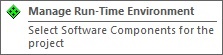
Figure 3: Accessing the Manage Run-Time Environment
Within the “Manage Run-Time Environment” window, we need to enable I2C (API): custom, device definitions, and a number of Native Driver components. This is shown in the following screen capture images.
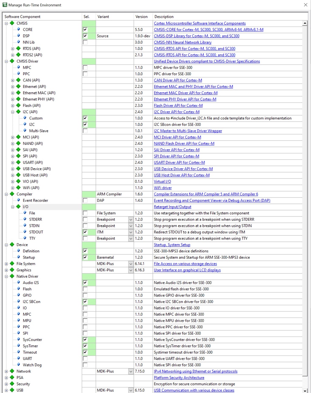
Figure 4: Selecting the required Run-time components
In addition, you need to add the following codes to “device_cfg.h”, assuming the project is running from Secure world. If the code is running from the Non-secure world, the “_S” suffix should be changed to “_NS”.
/* I2C_SBCon */
#define I2C0_SBCON_S
#define I2C0_SBCON_DEV              I2C0_SBCON_DEV_S

#define MPS3_I2S_S
#define MPS3_I2S_DEV                MPS3_I2S_DEV_S
Figure 5: Modification of device_cfg.h
As in most projects, we need to define the stack and heap sizes. With the SSE-300 MPS3 CMSIS-PACK, the definitions of HEAP_SIZE and STACK_SIZE are in region_limits.h.
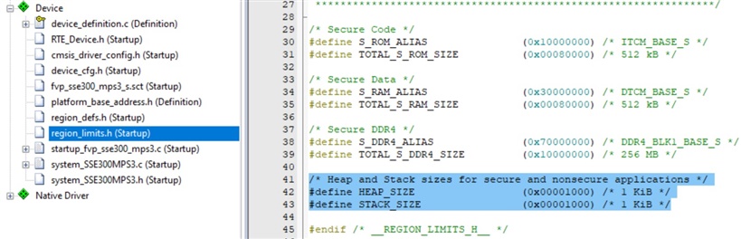
Figure 6: Stack and Heap sizes configuration
The linker setting should be configured to use the scatter file included in the SSE-300 MPS3 CMSIS-PACK (.\RTE\Device\SSE-300-MPS3\fvp_sse300_mps3_s.sct).
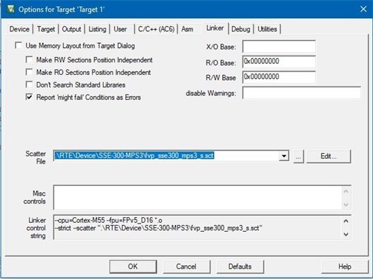
Figure 7: Scatter file setting
Finally, due to a limitation in current Keil MDK, the Debug Description in the debug setting need to be disabled.
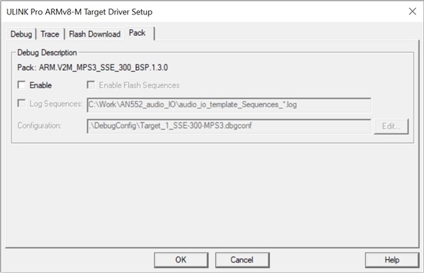
Figure 8: Disable Debug Description in debug settings.
With all these setups in place, the application code for setup up the audio to pass audio from audio-in to audio-out is as simple as the following:
#include "stdio.h"
#include "SSE300MPS3.h"
#include "cmsis_driver_config.h"
#include "audio_i2s_mps3_drv.h"
#include "audio_codec_mps3_an552.h"

void I2S_Handler(void);

int main(void)
{
  audio_init(); // Initialise the audio interface

  printf ("Audio interface initialized\n");
  while(1){
  __WFE();		// sleep while nothing is need to be sone
  }

} // end of main()

/************************************************************************/
/* I2S audio IRQ handler. Triggers at 48KHz.                            */
/************************************************************************/
void I2S_Handler(void) {
  // audio_i2s_mps3_sample_t contains left and right channels
  // This struct is defined in audio_i2s_mps3_drv.h
  struct audio_i2s_mps3_sample_t audio_in_sample;
  struct audio_i2s_mps3_sample_t audio_out_sample;
  int16_t left_val, right_val;

  // Read sample from ADC
  audio_in_sample = read_sample(&MPS3_I2S_DEV);
  // Convert to signed int16
  left_val  = (int16_t) (audio_in_sample.left_channel);
  right_val = (int16_t) (audio_in_sample.right_channel) ;

  // Output needs uint16_t (unsigned), therefore add 0x8000
  audio_out_sample.left_channel  = (uint16_t) (left_val + 0x8000);
  audio_out_sample.right_channel = (uint16_t) (right_val + 0x8000);

  // Write sample to DAC
  write_sample(&MPS3_I2S_DEV,audio_out_sample);
  return;
}
With this test code ready, we can operate the FPGA platform as an audio feed through. The input signal for line in is about 0.5V. If the output waveform is distorted, please check that the input signal is not too large. Please also note that the drivers might make use of the SysTick timer.
Before running codes with Helium® technology
Once we have got the audio input and output working, the next exciting step is to utilizing Helium technology to implement some real time audio processing. In the CMSIS-DSP repository, there is a Low Pass Filter example (https://arm-software.github.io/CMSIS_5/DSP/html/group__FIRLPF.html) and it sounds like a good starting point. However, before we implement the real-time filter project that there are a few things we need to setup:
Enables the Low-overhead Branch feature
The Low-overhead Branch (LOB) feature needs to be enabled to take advantage of this feature. This is done by setting the LOB bit (bit 19) in the Configuration and Control Register (Address 0xE000ED14), and then execute an DSB (Data Synchronization Barrier) and an ISB (Instruction Synchronization Barrier) instruction. By default the LOB bit in the CCR is reset to 0 and this bit. The setup step to set LOB to 1 is typically included in the SystemInit() function if you are using the CMSIS-CORE software framework.
If you are using CMSIS-CORE in your project:
  // Enable Loop and branch info cache
  SCB->CCR |= SCB_CCR_LOB_Msk;
  __DSB();
  __ISB();
If you are not using CMSIS-CORE in your project:
#define CCR_ADDR (0xE000ED14UL)
#define CCR  *(volatile unsigned int *) CCR_ADDR
#define __ISB()  __builtin_arm_isb(0xF)
#define __DSB()  __builtin_arm_dsb(0xF)
  CCR |= 0x00080000UL;
  __DSB();
  __ISB();
This control bit is banked between the Security State. Therefore, both Secure privileged software and Non-secure privileged software need to set this bit.
Enables the Extension Processing Unit (EPU)
In the Cortex-M55 processor, one of the key hardware unit called the Extension Processing Unit (EPU) is used for processing floating-point instructions and Helium instructions. By default, the EPU is disabled to save power. If you are using CMSIS-CORE software framework, the EPU is enabled within the SystemInit() function. An example of this setup step is in the example system_ARMCM55.c, which can be found in CMSIS 5 github : https://github.com/ARM-software/CMSIS_5/blob/develop/Device/ARM/ARMCM55/Source/system_ARMCM55.c
#if (defined (__FPU_USED) && (__FPU_USED == 1U)) || \
(defined (__ARM_FEATURE_MVE) && (__ARM_FEATURE_MVE > 0U))
SCB->CPACR |= ((3U << 10U*2U) | /* enable CP10 Full Access */
(3U << 11U*2U) ); /* enable CP11 Full Access */
__DSB();
__ISB();
#endif
Inside the code fragment that enables the EPU, two C pre-processing macros are used:
- The __ARM_FEATURE_MVE is a C macro set by the C compiler if the compilation options enabled the use of Helium instructions. To make sure that this C macro is setup correctly, you need to use a C compiler that support Arm C Language Extension (ACLE). Most of the C compilers that support Arm architecture support ACLE features.
- The __FPU_USED macro is generated inside “core_cm55.h” by detecting compilation options used.
With the above code fragment, the EPU is enabled if either floating-point instructions or Helium instructions can be generated.
Similar to the LOB bit in CCR, the enable bits for EPU are banked between Security State. In addition, if TrustZone security is used, Secure software must also setup:
- Non-secure Access Control Register (SCB->NSACR) to define if the Non-secure software has access to the EPU.
- Floating-Point Context Control Register (FPCCR) to define security settings.
Defines the power-saving scheme for the EPU
Depending on the system design, the Cortex-M55 processor might attempt to put the EPU into a retention when it is not used to save power. This can happen even when the EPU was enabled. After the EPU entered retention state, if the software executes an FPU or Helium instruction, the processor will wake up the EPU automatically. While this is beneficial to energy efficiency, and is completely transparent to software, the automatic power switching sequences could cause delays to the program’s operation and could therefore reduce performance. To avoid this performance penalty, change the ELPSTATE bits in the Core power domain Low Power State Register (CPDLPSTATE) to 0b00 (ON) or 0b01 (clock gated). Software should switch ELPSTATE bits back to 0b11 if the application does not require EPU, for example, when the device is going to enter a sleep mode.
This setup step has been included in the SystemInit() in system_SSE300MPS3.c:
/* Set CPDLPSTATE.CLPSTATE to 0, so PDCORE will not enter low-power state. Set
 CPDLPSTATE.ELPSTATE to 0, to stop the processor from trying to switch the EPU
 into retention state */
#define CPDLPSTATE_ADDR (0xE001E300UL)
#define CPDLPSTATE *(volatile unsigned int *) CPDLPSTATE_ADDR
  CPDLPSTATE &= 0xFFFFFF00UL;
Note 1: After a reset the value of CPDLPSTATE is 0x00000333, meaning that the processor would attempt to switch the EPU into retention state because ELPSTATE is set to OFF (0b11).
Note 2: CPDLPSTATE is NOT banked between Security State. If TrustZone is being used, Non-secure software does not have access to this register.
Getting started with a CMSIS-DSP example
One of the easiest ways to utilize Helium technology for signal processing is to use the CMSIS-DSP library (https://github.com/ARM-software/CMSIS_5/tree/develop/CMSIS/DSP), which has already been optimized for Helium. The CMSIS-DSP library contains a wide range of common DSP functions for various data types and is open source. It started out as a DSP library for the Arm Cortex-M processors, and now also cover Cortex-A processors.
Most of the application codes utilizing CMSIS-DSP codes for other Cortex-M processors can be reused on the Cortex-M55 processor without modification. There are, however, a few cases where some modifications are needed:
- When using biquad filter, the initialization function is different:
|
Non-Helium version |
Helium version |
|
arm_biquad_cascade_df1_init_f32 |
arm_biquad_cascade_df1_mve_init_f32 Note: It takes a new argument: pCoeffsMod. Its size is 32*numStages float32_t elements. |
- For FIR filter,
- Padding might be needed to adjust the size of filter coefficient array
- If using CMSIS-DSP library from CMSIS 5.8.0 - When using the Helium version of arm_fir_init_f32, the array size of coefficients must be a multiple of 4. Assumed the array size is 4a, and the number of filter tap is "numTaps", the additional coefficients (4a - numTaps) must be set to 0. "numTaps" is still set to its right value in the init function. It means that the filter library code may require to read more coefficients due to the vectorization and to avoid having to manage too many different cases in the code.
- If using CMSIS 5.7.0 - For Helium version of arm_fir_init_f32, the number of elements in the array must be a multiple of 16, with the additional coefficients set to 0.
- If using the latest development branch, please refer to the latest documentation.
- The state buffer must contain some additional temporary data used during the computation:
- If using CMSIS-DSP library from CMSIS 5.8.0 - The state buffer for arm_fir_init_f32 and arm_fir_f32 must contain some additional temporary data space. This additional memory space, which is the first 8*ceil(blockSize/8) samples, are temporary data used for the computation but is not used as FIR filter state. The remaining samples are the state of the FIR filter. So the state buffer has size numTaps + 8*ceil(blockSize/8) + blockSize - 1
- If using the latest development branch, please refer to the latest documentation.
- Padding might be needed to adjust the size of filter coefficient array
For example, the FIR filter coefficients in the Low Pass Filter example (which can be found in the CMSIS-DSP repository at https://arm-software.github.io/CMSIS_5/DSP/html/group__FIRLPF.html) is defined as:
(FIR coefficients and state buffer declarations for Cortex-M processors without Helium).
…
#define NUM_TAPS 29
…
const float32_t firCoeffs32[NUM_TAPS] = {
-0.0018225230f, -0.0015879294f, +0.0000000000f, +0.0036977508f,
+0.0080754303f, +0.0085302217f, -0.0000000000f, -0.0173976984f,
-0.0341458607f, -0.0333591565f, +0.0000000000f, +0.0676308395f,
+0.1522061835f, +0.2229246956f, +0.2504960933f, +0.2229246956f,
+0.1522061835f, +0.0676308395f, +0.0000000000f, -0.0333591565f,
-0.0341458607f, -0.0173976984f, -0.0000000000f, +0.0085302217f,
+0.0080754303f, +0.0036977508f, +0.0000000000f, -0.0015879294f,
-0.0018225230f
};
…
/* -------------------------------------------------------------------
 * Declare State buffer of size (numTaps + blockSize - 1)
 * ------------------------------------------------------------------- */
static float firStateF32_Left[BLOCK_SIZE + NUM_TAPS - 1];
static float firStateF32_Right[BLOCK_SIZE + NUM_TAPS - 1];
When it is ported to a Cortex-M55 processor system with Helium, and assumed we are using CMSIS-DSP in CMSIS version 5.8, we should change the code as follows:
(FIR coefficients and state buffer declarations for Cortex-M processors with Helium).
…
#define NUM_TAPS 29
…
const float32_t firCoeffs32[32] = {
-0.0018225230f, -0.0015879294f, +0.0000000000f, +0.0036977508f,
+0.0080754303f, +0.0085302217f, -0.0000000000f, -0.0173976984f,
-0.0341458607f, -0.0333591565f, +0.0000000000f, +0.0676308395f,
+0.1522061835f, +0.2229246956f, +0.2504960933f, +0.2229246956f,
+0.1522061835f, +0.0676308395f, +0.0000000000f, -0.0333591565f,
-0.0341458607f, -0.0173976984f, -0.0000000000f, +0.0085302217f,
+0.0080754303f, +0.0036977508f, +0.0000000000f, -0.0015879294f,
-0.0018225230f, 0.0f, 0.0f, 0.0f
};
…

// If using CMSIS 5.70 or later
/* -------------------------------------------------------------------
 * Declare State buffer of size (numTaps + blockSize - 1)
 * ------------------------------------------------------------------- */
//static float firStateF32_Left[BLOCK_SIZE + NUM_TAPS - 1];
//static float firStateF32_Right[BLOCK_SIZE + NUM_TAPS - 1];

// If using CMSIS 5.80 or later
/* -------------------------------------------------------------------
 * Declare State buffer of size (numTaps + 2*blockSize - 1)
 * ------------------------------------------------------------------- */
static float firStateF32_Left[BLOCK_SIZE*2 + NUM_TAPS - 1];
static float firStateF32_Right[BLOCK_SIZE*2 + NUM_TAPS - 1];
While the example on CMSIS-DSP github repository (https://arm-software.github.io/CMSIS_5/DSP/html/group__FIRLPF.html) demonstrates how to use CMSIS-DSP library functions to create a Low Pass Filter, the processing is carried out using predefined input data. This arrangement is not suitable for real-time application, and further work is required to create a real-time filter based on this example code. To make the code suitable for real-time filter application, a common technique is to change the data buffers into a pair of ping-pong buffers - one set of buffer to handle data input/output while another set is used by the filter processing. When the input buffer is filled and the output buffer is emptied, the buffers are switched over and the filter processing is restarted.
To handle stereo audio, each set of buffers contain left and right channels. The result code example is as follows:
#include "stdio.h"
#include "SSE300MPS3.h"
#include "arm_math.h"
#include "cmsis_driver_config.h"
#include "audio_i2s_mps3_drv.h"
#include "audio_codec_mps3_an552.h"

void I2S_Handler(void);

extern void read_sample(int16_t *left, int16_t *right);
extern void play_sample(int16_t *left, int16_t *right);


#define BLOCK_SIZE            32
#define NUM_TAPS              29

// Ping Pong Buffer
static float InputBufferA_Left[BLOCK_SIZE], InputBufferB_Left[BLOCK_SIZE];
static float OutputBufferA_Left[BLOCK_SIZE], OutputBufferB_Left[BLOCK_SIZE];
static float InputBufferA_Right[BLOCK_SIZE], InputBufferB_Right[BLOCK_SIZE];
static float OutputBufferA_Right[BLOCK_SIZE], OutputBufferB_Right[BLOCK_SIZE];
volatile int PingPongState = 0, BlockCounter = 0 , StatusFlag=0;

// If using CMSIS 5.8.0 or later

/* -------------------------------------------------------------------

 * Declare State buffer of size (numTaps + 2*blockSize - 1)
 * ------------------------------------------------------------------- */

static float firStateF32_Left[2*BLOCK_SIZE + NUM_TAPS - 1];

static float firStateF32_Right[2*BLOCK_SIZE + NUM_TAPS - 1];

/* ----------------------------------------------------------------------

** FIR Coefficients buffer generated using fir1() MATLAB function.

** fir1(28, 6/24)

** ------------------------------------------------------------------- */

const float firCoeffs32[32] = {
  -0.0018225230f, -0.0015879294f, +0.0000000000f, +0.0036977508f,
  +0.0080754303f, +0.0085302217f, -0.0000000000f, -0.0173976984f,
  -0.0341458607f, -0.0333591565f, +0.0000000000f, +0.0676308395f,
  +0.1522061835f, +0.2229246956f, +0.2504960933f, +0.2229246956f,
  +0.1522061835f, +0.0676308395f, +0.0000000000f, -0.0333591565f,
  -0.0341458607f, -0.0173976984f, -0.0000000000f, +0.0085302217f,
  +0.0080754303f, +0.0036977508f, +0.0000000000f, -0.0015879294f,
  -0.0018225230f, 0.0f,0.0f,0.0f
};

int main(void)
{
  arm_fir_instance_f32 S_Left;
  arm_fir_instance_f32 S_Right;

  int32_t i;
  uint32_t blockSize = BLOCK_SIZE;
  for (i=0;i<BLOCK_SIZE;i++) {
    // Clear output buffers
    OutputBufferA_Left[i]=0;
    OutputBufferB_Left[i]=0;
    OutputBufferA_Right[i]=0;
    OutputBufferB_Right[i]=0;
  }
  audio_init();        // Initialise the audio inteface

  /* Call FIR init function to initialize the instance structure. */
  arm_fir_init_f32(&S_Left, NUM_TAPS, (float32_t *)&firCoeffs32[0], &firStateF32_Left[0], blockSize);
  arm_fir_init_f32(&S_Right, NUM_TAPS, (float32_t *)&firCoeffs32[0], &firStateF32_Right[0], blockSize);

  printf ("Audio interface initialized\n");
  while(1){
    if (StatusFlag!=0){ // Wait until Status Flag is set
      StatusFlag=0; // Clear status flag
      if (PingPongState) {
        // Process Buffer A
        arm_fir_f32(&S_Left, &InputBufferA_Left[0], &OutputBufferA_Left[0], blockSize);
        arm_fir_f32(&S_Right, &InputBufferA_Right[0], &OutputBufferA_Right[0], blockSize);
      } else {
        // Process Buffer B
        arm_fir_f32(&S_Left, &InputBufferB_Left[0], &OutputBufferB_Left[0], blockSize);
        arm_fir_f32(&S_Right, &InputBufferB_Right[0], &OutputBufferB_Right[0], blockSize);
      }
      if (StatusFlag!=0) {
        // Overflow ERROR
        __BKPT(0); // Breakpoint
      }
    }
  __WFE(); // sleep while nothing is need to be sone
  }
} // end of main()

/************************************************************************/
/* I2S audio IRQ handler. Triggers at 48KHz.                             */
/************************************************************************/

void I2S_Handler(void) {
  // audio_i2s_mps3_sample_t contains left and right channels
  // This struct is defined in audio_i2s_mps3_drv.h
  struct audio_i2s_mps3_sample_t audio_in_sample;
  struct audio_i2s_mps3_sample_t audio_out_sample;
  // Samples from both audio channels
  int16_t left_channel_in, right_channel_in;
  int16_t left_channel_out, right_channel_out;

  // Read sample from ADC
  audio_in_sample = read_sample(&MPS3_I2S_DEV);
  // Convert to signed int16
  left_channel_in  = (int16_t) (audio_in_sample.left_channel);
  right_channel_in = (int16_t) (audio_in_sample.right_channel) ;
  // Read sample from ADC
  if (PingPongState) {
    InputBufferB_Left[BlockCounter] = left_channel_in;
    InputBufferB_Right[BlockCounter] = right_channel_in;
    //left_channel_out = left_channel_in;
    //right_channel_out = right_channel_in;
    left_channel_out = (int16_t) OutputBufferB_Left[BlockCounter];
    right_channel_out = (int16_t) OutputBufferB_Right[BlockCounter];
  } else {
    InputBufferA_Left[BlockCounter] = left_channel_in;
    InputBufferA_Right[BlockCounter] = right_channel_in;
    //left_channel_out = left_channel_in;
    //right_channel_out = right_channel_in;
    left_channel_out = (int16_t) OutputBufferA_Left[BlockCounter];
    right_channel_out = (int16_t) OutputBufferA_Right[BlockCounter];
  }
  BlockCounter++;
  if (BlockCounter>= BLOCK_SIZE) {
    BlockCounter=0; // Reset Block counter
    StatusFlag = 1;  // Start processing
    PingPongState = PingPongState ^ 1; // Toggle Ping Pong state
  }

  // Output needs uint16_t (unsigned), therefore add 0x8000
  audio_out_sample.left_channel  = (uint16_t) (left_channel_out + 0x8000);
  audio_out_sample.right_channel = (uint16_t) (right_channel_out + 0x8000);

  // Write sample to DAC
  write_sample(&MPS3_I2S_DEV,audio_out_sample);
  return;

}
Note: When using source version of CMSIS-DSP library in your Keil MDK project, please select a high optimization level for the C compiler (for example, -Ofast). This is needed to ensure that the CMSIS-DSP library functions are compiled using optimized settings. With default optimization level (-O1) many Helium-related optimizations are disabled and can result suboptimal DSP performance.
Visualizing the data in Keil MDK
To make sure that the filter is working, an input waveform of square wave with pulses is generated with a signal generator and the inputs and outputs can be observed using an oscilloscope. While that works well, it would be even better if we can visualize the inputs and results inside the debug tool. This can be done by utilizing the data trace capability in the Cortex-M55’s Data Watchpoint and Trace (DWT) unit, and the Analyzer feature in Keil MDK. To do that, I add the following data declarations in the audio filter code:
  // Declare as volatile so that Logic Analyzer can see them
  volatile int16_t v_left_channel_in, v_right_channel_in;
  volatile int16_t v_left_channel_out, v_right_channel_out;
And in the I2S_Handler, the extra data variables declared are updated for each data sample:
void I2S_Handler(void) {
  // audio_i2s_mps3_sample_t contains left and right channels
  // This struct is defined in audio_i2s_mps3_drv.h
  struct audio_i2s_mps3_sample_t audio_in_sample;
  struct audio_i2s_mps3_sample_t audio_out_sample;
  // Samples from both audio channels
  int16_t left_channel_in, right_channel_in;
  int16_t left_channel_out, right_channel_out;

  // Read sample from ADC
  audio_in_sample = read_sample(&MPS3_I2S_DEV);
	// Convert to signed int16
  left_channel_in  = (int16_t) (audio_in_sample.left_channel);
  right_channel_in = (int16_t) (audio_in_sample.right_channel) ;

  // Read sample from ADC
  if (PingPongState) {
    InputBufferB_Left[BlockCounter] = left_channel_in;
    InputBufferB_Right[BlockCounter] = right_channel_in;
    //left_channel_out = left_channel_in;
    //right_channel_out = right_channel_in;
    left_channel_out = (int16_t) OutputBufferB_Left[BlockCounter];
    right_channel_out = (int16_t) OutputBufferB_Right[BlockCounter];
  } else {
    InputBufferA_Left[BlockCounter] = left_channel_in;
    InputBufferA_Right[BlockCounter] = right_channel_in;
    //left_channel_out = left_channel_in;
    //right_channel_out = right_channel_in;
    left_channel_out = (int16_t) OutputBufferA_Left[BlockCounter];
    right_channel_out = (int16_t) OutputBufferA_Right[BlockCounter];
  }
  BlockCounter++;
  if (BlockCounter>= BLOCK_SIZE) {
    BlockCounter=0; // Reset Block counter
    StatusFlag = 1;  // Start processing
    PingPongState = PingPongState ^ 1; // Toggle Ping Pong state
   }
  // Output needs uint16_t (unsigned), therefore add 0x8000
  audio_out_sample.left_channel  = (uint16_t) (left_channel_out + 0x8000);
  audio_out_sample.right_channel = (uint16_t) (right_channel_out + 0x8000);

   // Write sample to DAC
  write_sample(&MPS3_I2S_DEV,audio_out_sample);

  v_left_channel_in = left_channel_in;
  v_left_channel_out = left_channel_out;
  v_right_channel_in = right_channel_in;
  v_right_channel_out = right_channel_out;

  return;
}
After the code is compiled, at the beginning of the debug session I can right-click on these variables and add them to Analyzer to be traced:
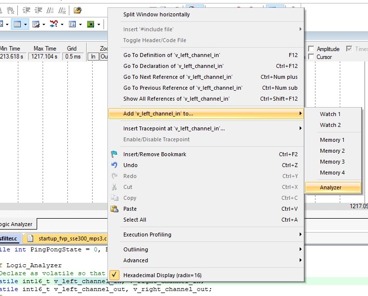
Figure 9: Adding a variable to the Analyzer window
Then I can open the Logic Analyzer window, and visualize the filter’s inputs and output:
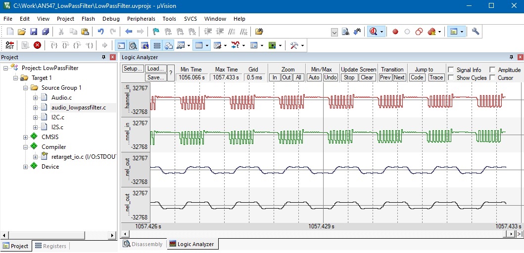
Figure 10: Using Logic Analyzer window to visualize signal data.
In the screenshot, the two signals on the top are the inputs (left and right) and the of the following two signals are outputs. The DWT support data tracing for up to four data variables. Please note that when using this feature, it is best to use a debug probe that supports parallel trace port operations (for example, Keil ULINKpro). While Serial Wire Output (SWO) output mode can support data trace, the available trace bandwidth when using SWO might not be sufficient if the amount of trace data generate is significant.
Create other CMSIS-DSP filters
Of course, there is often a need to design a new filter as the filter characteristic in the available examples might not fit your requirement. The details of filter design are out of the scope for this document. However, there are plenty of resources available on the Internet, and there are filter design tools that make this much easier. For example, an Arm ecosystem partner called Advanced Solutions Nederland B.V. (ASN, www.advsolned.com ) has enhanced their filter design tool "ASN Filter Designer" so now it can generate filter codes based on CMSIS-DSP for the Cortex-M55 processor out of the box.
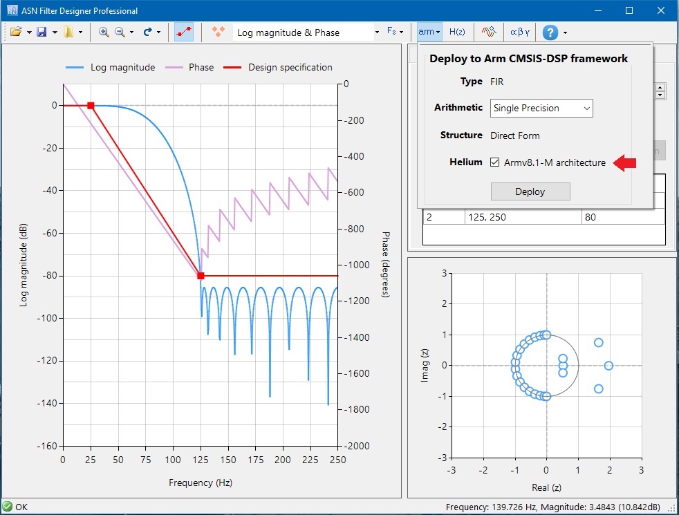
Figure 11: Select Helium option when generating filter codes for Cortex-M55 processor in ASN Filter Designer.
Generate Helium codes using compiler’s auto-vectorization feature
Arm Compiler supports auto-vectorization feature which can utilize Helium technology in code generation. As a result, even C/C++ application codes (e.g. general data processing) can take advantage of the Helium technology. In Arm Compiler 6, auto-vectorization is enabled for “-O2” or previous. For best performance, please set compiler optimization level to “-Ofast” or previous. (“-O2” and lower optimization does not give all the performance benefits). You can also explicitly turn auto-vectorization on and off:
|
Command-line option |
Description |
|
-fvectorize |
Enable auto-vectorisation (default when using -O2 and previous) |
|
-fno-vectorize |
Disable auto-vectorisation |
Arm Compiler 6 (and LLVM based compiler) also provides vectorization diagnostic in the following command-line options:
-Rpass=loop-vectorize -Rpass-analysis=loop-vectorize -Rpass-missed=loop-vectorize
Performance analysis
After creating a signal processing function, often it is important to measure the performance. The simplest method is to use a cycle counter to measure how many clock cycles a DSP function need. For example, we can use the SysTick timer inside the processor if this is not used by other software (for example, RTOS). The code to handle this measurement could be written as:
  uint32_t start_cycle, stop_cycle, total_cycle;
  uint32_t worst_cycle=0;
  …
  SysTick->CTRL = 0; // Disable SysTick
  SysTick->VAL =  0; // Write any value to clear
  SysTick->LOAD = 0x00FFFFFFUL; // Maximum reload value
  SysTick->CTRL = 5; // Enable, internal clock
  while (SysTick->VAL==0); // wait until started
  start_cycle = SysTick->VAL; // Save start cycle
  …  // Code being benchmarked
  stop_cycle  = SysTick->VAL;
  SysTick->CTRL = 0; // Stop
  total_cycle = start_cycle-stop_cycle; // SysTick is a decrement counter
  if (total_cycle > worst_cycle) {
    worst_cycle = total_cycle;
    printf ("%d\n", worst_cycle); // Report
  }
  …
The code measures the clock cycles taken for every round of the DSP processing. The worst_cycle variable stores the worst case and if in an iteration the number of clock cycles measured is higher than previous worst case, this variable is updated and report in the console.
This approach is fine for simple benchmarks. However, there are cases where detail breakdown of execution time is useful for software optimization. Many Cortex-M processors support a feature called Embedded Trace Macrocell (ETM) for instruction tracing. If you have a debug probe that support ETM trace like Keil ULINK Pro, you can enable ETM trace and that gives you a range of profiling capability. To enable ETM trace, open the project’s debug probe settings, and you can see the ETM trace option on the top right-hand corner:
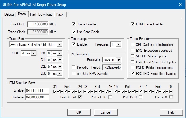
Figure 12: Enabling ETM trace feature in debug adaptor settings.
In some cases (depending on the hardware that you used), you might find that some of the trace is corrupted or the trace is not working reliably. If this happens, you need to adjust the trace sampling timing option on the left of the configuration option window. In figure 13, the CLK timing setting is modified to 4.9ns for my system (default is 0ns). Depending on the timing characteristics of the trace probe used, you might need to try out different settings to see what is best for you.
After enabling the ETM, you can then use the Performance Analyzer feature to see the project’s execution profile:
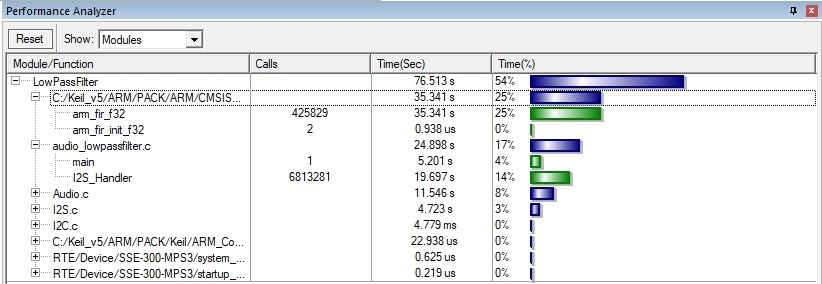
Figure 13: Performance Analyzer window in Keil MDK
The chart in the Performance Analyzer is updated in real-time using ETM trace information. In this example, we see that the processor is active only around half of the time:
- 25% of the execution time is used for the FIR filters (for 2 audio channels).
- The remaining execution time are spent in the audio interface control code, which includes the I2S interface interrupt handler.
There are many other useful analysis tools inside Keil MDK. You can find information about those features in the Keil website: https://www.keil.com/support/man/docs/uv4/uv4_db_dbg_win_dialogs.htm.
Summary
With the release if the Cortex-M55 FPGA image, software developers can develop a range of signal processing applications using:
- the Arm MPS3 FPGA board,
- the CMSIS-DSP library,
- Arm development solutions such as Keil MDK
- other solutions from the Arm ecosystem
With the setup demonstrated in this article, software developer can enable the use of Helium technology in their signal processing and application codes. Arm toolchain can also enable them to analyse the performance of the system in great details. For more information about optimizing software for the Cortex-M55 processor, please visit this page: https://community.arm.com/arm-community-blogs/b/architectures-and-processors-blog/posts/armv8_2d00_m-based-processor-software-development-hints-and-tips

By Joseph Yiu
Re-use is only permitted for informational and non-commercial or personal use only.
