Vulkan synchronization on Mali GPUs: Pipeline barriers, hardware behavior, and best practices
Learn how Vulkan barriers map to Mali GPUs, how CSF streams interact, and how to optimize synchronization for better GPU utilization.

Modern graphics APIs such as Vulkan and D3D12 are more explicit than their predecessors. Tasks that GPU drivers handled are now the responsibility of the application. A key example is GPU work synchronization.
Vulkan provides several synchronization primitives: barriers, events, semaphores, and fences. In this blog post, I focus on barriers since they are used most often and look at how they map on to Mali hardware. The goal is not to explain how Vulkan barriers work in general. Instead, to show how Mali GPUs implement synchronization and how you can optimize for them.
This blog post covers Valhall 3rd generation and later GPUs that use a Command Stream Frontend (CSF). Older architectures handle synchronization differently and are not discussed here. The focus is on Mali-G710 and its siblings (G610, G510, G310) up to Mali G1 and its variants (Ultra, Premium, Pro).
The material in this blog post assumes that you are familiar with Vulkan and targets advanced users.
We examine the Vulkan command vkCmdPipelineBarrier and its modernized version vkCmdPipelineBarrier2. vkCmdPipelineBarrier2, along with its associated inputs, VkAccessFlags2, VkPipelineStageFlags2, provides functionality that is almost identical to vkCmdPipelineBarrier. As a result, everything described in this blog post applies equally to both commands unless explicitly stated otherwise. The parameters to the barrier commands describe three pieces of information:
- Which pipeline stages need to finish before new work starts. This is expressed by the VkPipelineStageFlags /VkPipelineStageFlags 2.
- Which GPU caches need to be flushed or invalidated. This is expressed by VkAccessFlags/ VkAccessFlags2.
- Which GPU (sub) resources are involved and, more importantly, the transitions from one image state to another. This is where VkImageLayout comes into play.
Pipeline stage dependencies
However in practice, most GPUs, including Arm’s, perform implicit synchronization for several of these stages. As a result, VkPipelineStageFlags is often more fine-grained than the underlying hardware requires.
On Valhall 3rd-generation GPUs, the Command Stream Frontend (CSF) is split into four distinct streams. Each stream parses command lists and dispatches tasks to other units. Details follow later in this blog post.
The table below shows the four CSF streams and the corresponding VkPipelineStageFlags they handle:
| CSF stream | Responsibilities | Relevant VkPipelineStageFlag Bits |
| Transfer stream | Handles transfer operations such as buffer and image copies | TRANSFER_BIT |
| Compute stream | Parses compute dispatches as well as ray tracing commands | COMPUTE_SHADER_BIT, ACCELERATION_STRUCTURE_BUILD _BIT*, RAY_TRACING_SHADER_BIT |
| Geometry stream | Parses the geometry part (e.g. vertex shading) of drawcalls | DRAW_INDIRECT_BIT to GEOMETRY_SHADER_BIT as well as TRANSFORM_FEEDBACK_BIT_EXT |
| Fragment stream | Parses the epilogue of a renderpass where all fragment shading related operations belong to | FRAGMENT_SHADER_BIT to COLOR_ATTACHMENT_OUTPUT_BIT |
*: ACCELERATION_STRUCTURE_BUILD _BIT might be running on transfer stream on older driver releases
There is also a rarely used stream that parses internal commands for tessellation, geometry shaders, and transform feedback. For practical purposes, we can ignore it.
A Vulkan command buffer contains up to four command lists, one per command stream. Each command stream parses its corresponding command list independently from the other streams. It breaks each command into tasks and these tasks are then dispatched to three hardware queues:
- Main phase queue (also known as Fragment queue on pre-Gx20 GPUs): This queue executes all fragment shading. On Gx20 and later GPUs it executes part of vertex shading as well. Work in this queue primarily comes from render passes and, in some cases, from transfer commands. Most copies that have images as destination are implemented using fragment jobs. As a result, some image copies are executed in the main pass queue.
- Binning phase queue (also called the Vertex queue on pre-Gx20 GPUs): This queue handles primitive binning. On older architectures before Gx20, it also handles all vertex shading. Starting with Gx20, only part of the vertex shading pipeline runs in the binning phase. The remainder shifts to the main phase, as noted earlier.
- Compute phase queue: This queue runs all compute workloads. It also handles certain transfer commands. Any transfer operation targeting a buffer is implemented as a compute dispatch. In rare cases, transfers targeting images also run as compute dispatches. Both vkCmdBuildAccelerationStructures and vkCmdTraceRays are executed as compute dispatches.
The hardware can run the main phase in parallel with binning and compute. However, binning and compute cannot overlap with each other. Each queue can also execute multiple commands concurrently. The actual level of concurrency is ultimately constrained by hardware limits.
Vulkan pipeline barriers describe cross-stream dependencies and intra-stream dependencies. For example, a barrier with source VK_PIPELINE_STAGE_TRANSFER_BIT and destination VK_PIPELINE_STAGE_COMPUTE_SHADER_BIT is a cross-stream dependency. A barrier from VK_PIPELINE_STAGE_FRAGMENT_SHADER_BIT to VK_PIPELINE_STAGE_FRAGMENT_SHADER_BIT is an inta -stream dependency.
A good practice is to model barriers in terms of the four CSF streams. At a minimum, the application should expose four stages:
- Transfer
- Compute
- Geometry
- Fragment
Since the compute stream handles multiple pipeline stages, add two additional stages when the application supports ray tracing. Ray tracing commands can overlap with other compute work, subject to hardware limits that govern intra-queue parallelism. Keeping them separate from regular compute avoids unnecessary blocking of work. If the application supports ray tracing, add the following stages:
- Acceleration structure build
- Trace rays
Running fragment and non-fragment work concurrently is a key optimization on Mali GPUs. Workloads that run in the main phase queue typically use different hardware units from workloads in the other two queues. Executing them in parallel improves overall GPU utilization. For example, geometry processing interacts heavily with the load/store unit to fetch vertices. It also uses fixed-function blocks such as the tiler because Mali is a tile-based architecture. In contrast, fragment shading relies more on the texture unit, is often ALU-bound. It uses fixed-function units like the rasterizer and tile buffer. GPU utilization improves when all units work in parallel.
Running fragment and non-fragment work concurrently is only possible when the application uses precise, non-conservative barriers. If an application treats fragment and geometry stages as a single graphics stage, much of the potential overlap is lost. Avoid fragment to non-fragment barriers. For example, placing a barrier from fragment to vertex after a render pass will force the non-fragment work to wait until all fragment processing completes. This creates a pipeline bubble.
Many GPU vendors recommend merging barriers. However, there are rare cases where doing so can introduce negative side effects. For example, consider an application with one barrier from transfer to vertex and another from fragment to fragment. If the application merges these into a single barrier, the dependency becomes transfer and fragment to vertex and fragment. Vertex shading then depends on fragment shading. This dependency is unnecessary and reduces pipelining efficiency because of the fragment to non-fragment dependency.
One solution is to use vkCmdPipelineBarrier2, introduced in VK_KHR_synchronization2 and which became core in Vulkan 1.3. This command allows setting pipeline dependencies per resource. The driver can then merge or split barriers intelligently.
The final recommendation is to use the Streamline profiler, which is part of Arm Performance Studio. This tool helps you identify and analyze pipeline bubbles. One useful view is the Mali Timeline scheduler trace view. You can capture Mali Timelines alongside hardware counters. This view shows GPU jobs on a timeline and organized by the stream they belong to. On devices with drivers newer than R51, and when using the latest Arm Performance Studio, you can annotate the timeline boxes with Vulkan debug markers via VK_EXT_debug_utils.

By looking at Streamline’s timelines you can identify overlapping opportunities and either fix overly conservative barriers or re-arrange work for better pipelining.
Access masks and caches
As noted earlier, VkAccessFlags often help the driver decide which caches to flush or invalidate. Fields such as offset and size in VkBufferMemoryBarrier, or VkImageSubresourceRange, help determine the affected memory ranges. Mali GPUs have multiple caches. From a Vulkan perspective only three are relevant to the application: the Load/Store Cache (LSC), the texture cache, and the L2 cache. Coherency is guaranteed only for the LSC. The driver manages the other caches. The hardware does not support range-based flushes or invalidations. It always flushes the entire cache or nothing.
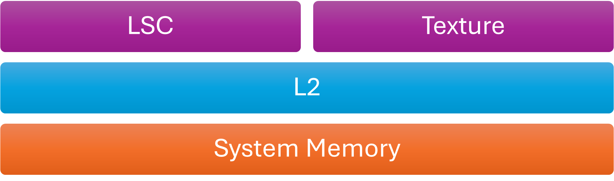
Cache Hierarchy
Flush the L2 cache when dstAccessMask is VK_ACCESS_HOST_READ_BIT. In other words, write the GPU’s L2 cache back to system memory before the CPU safely reads memory modified by the GPU. Mali caches are usually not coherent with CPU caches unless the SoC implements I/O coherency, which solves part of the coherency problem. These device-to-host data transfers are usually called readbacks. For example, the GPU feeds the CPU with visibility information, such as occlusion query testing results or a downsampled depth buffer, also known as a coverage buffer. In practice, most drivers flush caches at the end of each submission, even if the application does not explicitly request it with a barrier. The Mali driver also flushes the L2 cache at the end of every submission.
vkd3d-proton, which is Valve’s D3D12-to-Vulkan translation layer, submits a tiny command buffer at the tail of each vkQueueSubmit. Each vkQueueSubmit submits the user provided command buffers and this additional small command buffer. This buffer contains a single barrier that flushes GPU caches and make memory visible to the host. This step is required because, unlike Vulkan, D3D12 does not have the notion of host access. However, vkd3d-proton checks the driver string and skips this additional command buffer on some drivers. On those drivers, the flush already happens. Mali drivers also follow this implicit flush behavior.
VK_ACCESS_HOST_READ_BIT and VK_ACCESS_HOST_WRITE_BIT in the first synchronization scope (srcAccessMask) also interact with the GPU L2 cache. However, their use is rare because Vulkan already requires GPU caches to be implicitly invalidated before each submission. Each submission starts from a clean slate as defined by the Vulkan specification. Therefore, barriers involving HOST access in the first synchronization scope provide little value. For that reason, we will not cover this case further.
The second cache that is a little bit special for Mali is the texture cache. It requires manual invalidation. It is a read only cache so it does not get flushed. The driver analyzes the VkAccessFlags to determine whether the first synchronization scope writes to textures and the second synchronization scope samples textures. In that case, the driver inserts a texture cache invalidation.
| 1st synchronization scope. VkAccessFlags that imply writing to textures. |
2nd synchronization scope. VkAccessFlags that imply sampling textures. |
| SHADER_WRITE_BIT COLOR_ATTACHMENT_WRITE_BIT DEPTH_STENCIL_ATTACHMENT_WRITE_BIT TRANSFER_WRITE_BIT MEMORY_WRITE_BIT GENERAL_BIT |
SHADER_READ_BIT |
VkAccessFlags appear in buffer barriers (VkBufferMemoryBarrier), image barriers (VkImageMemoryBarrier) and in general barriers (VkMemoryBarrier). Only image and general memory barriers affect textures. As a result, these are the only two barrier types that interact with the texture cache.
As we briefly mentioned above, Mali hardware does not support fine-grained cache invalidation or flushing. Cache maintenance operates at the whole-cache level. The Vulkan API offers fine-grained controls for image and especially buffer barriers. For example, VkBufferMemory barrier accepts offset and range parameters that the driver does not use. This means that detailed resource tracking is unnecessary on Mali GPUs.
Image layouts
VkImageLayout parameters are part of VkImageMemoryBarrier and describe changes in image state. For some GPUs, images can exist in various states, such as compressed or uncompressed. The driver must transition them from one state to another. Images in Mali do not change state. They are created as either compressed or uncompressed. However, that does not mean that image layouts are less useful.
Transaction Elimination (TE) is a bandwidth optimization Mali GPUs use during render passes. Since Mali is tile-based, fragment shading operates tile by tile. After shading completes for a tile, the tile buffer, which contains color, depth, and stencil data, is written to the attachment image.
Transaction Elimination avoids writing color data when the data has not been changed. Before writing a tile, the hardware computes a hash of the tile color and compares it with the stored hash for the corresponding region of the color attachment.
- If the hashes differ, the tile is flushed to RAM and the attachment’s hash is updated.
- If the hashes match, the flush is skipped, reducing both bandwidth and power consumption.
This optimization is especially effective for mostly static 2D content, such as user interfaces. For highly dynamic content, such as 3D games, the benefits are more limited. This blog post focuses only on how Transaction Elimination interacts with barriers. For more information, see the Transaction Elimination documentation.
The tile hashes that Transaction Elimination uses are treated as image metadata. Certain pipeline barriers can invalidate these hashes. For example, if a compute shader writes to an image, its Transaction Elimination metadata becomes invalid because image stores do not update tile hashes. Only render pass attachment writes updates tile hashes. As a result, when the driver encounters a barrier that transitions an image from VK_IMAGE_LAYOUT_GENERAL to VK_IMAGE_LAYOUT_COLOR_ATTACHMENT_OPTIMAL, it assumes that image stores may have modified the image. The driver then invalidates the hashes before the next render pass.
A similar case occurs when transitioning from VK_IMAGE_LAYOUT_UNDEFINED. Since the undefined layout discards any knowledge of the previous image state, the driver must also invalidate the tile hashes before the image can be used again.
The Mali Best Practices Guide describes the conditions that trigger image metadata invalidation and the cases where images cannot use hash metadata, such as multi-sampled images. If your workload benefits from Transaction Elimination, a good practice is to track image state across frames and avoid unnecessary layout transitions. Especially transitions from VK_IMAGE_LAYOUT_UNDEFINED.
With VK_KHR_unified_image_layouts, the Vulkan working group moved one step toward making the API easier to use. Unified image layouts eliminate most layout transitions and enable VK_IMAGE_LAYOUT_GENERAL to be used in most cases. This change also affects how the Mali driver handles Transaction Elimination hash invalidation. On drivers that support VK_KHR_unified_image_layout, and when the application enables this extension, barriers no longer control Transaction Elimination. Instead, the driver determines this behaviour at image creation time. If you create the image with a combination of the following usage flags it might benefit from Transaction Elimination:
- VK_IMAGE_USAGE_TRANSFER_SRC_BIT
- VK_IMAGE_USAGE_SAMPLED_BIT
- VK_IMAGE_USAGE_COLOR_ATTACHMENT_BIT
- VK_IMAGE_USAGE_TRANSIENT_ATTACHMENT_BIT
- VK_IMAGE_USAGE_INPUT_ATTACHMENT_BIT
- VK_IMAGE_USAGE_TRANSFER_DST_BIT
- VK_IMAGE_USAGE_DEPTH_STENCIL_ATTACHMENT_BIT
- VK_IMAGE_USAGE_HOST_TRANSFER_BIT
Conclusion
By examining how Mali GPUs handle synchronization in Vulkan, we have outlined several practices that can help applications run more efficiently. The key practices are as follows:
- Group GPU work into at least six pipeline stages: transfer, compute, geometry, fragment, acceleration structure build, trace rays.
- Bundle barriers together but also use vkCmdPipelineBarrier2 with accurate pipeline stages for each resource.
- Use Streamline profiler with timelines to identify pipeline bubbles and also get ideas on how to re-arrange passes for better pipelining.
- For buffers, just use VkBufferMemoryBarrier and set the offset field to 0 and the size to VK_WHOLE_SIZE. No need to be more fine-grained than that. Try not to include the same buffer more than once to avoid adding additional driver overhead.
- For images, use VkImageMemoryBarrier and try to be as specific as possible.
- Try to avoid general barriers (VkMemoryBarrier) since those may invalidate the texture cache even if it is not the user’s intent.
- Try to minimize the texture cache invalidations. A good way is to minimize the vkCmdPipelineBarrier commands by using a single pipeline barrier to express multiple memory barriers.
- Regarding HOST access flags, Mali does not require them for the majority of use-cases. However, to maintain full spec compliance, the application can place a barrier that contains HOST_READ in the second synchronization scope of the last command buffer in each submission.
- If your application is a mostly static UI or the rendering output remains largely unchanged, read the best practices for how to benefit from Transaction Elimination.
Re-use is only permitted for informational and non-commercial or personal use only.
